
Pressure and Pump
Pressure & Pump is step 3 of Details. It works out what the pump has to do, sizes the pipes of the pressure network, picks a pump and sets the dose. Only systems with a dose tank have this step.
The step reads the force main, the manifolds and the laterals drawn on the map. Under the step bar, links jump to each section: Pump duty, Force main, Zone 1, Pump, Dosing and Dosing text.
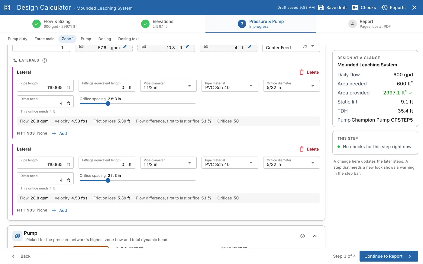
What the pump has to do
The Pump duty section gives the two numbers the pump is picked for:
- Required flow. The flow the pump must deliver.
- Total dynamic head (TDH). What the pump must push against: the static lift, the friction in the force main, the valve and the zone, and the head the zone needs at its far end.
The bigger either one, the bigger the pump. The section also shows:
| Value | What it is |
|---|---|
| Static lift | The height the pump lifts the effluent, from step 2's elevations. |
| Max zone loss | The friction loss of the zone with the most loss. |
| Max zone distal head | The highest pressure any zone needs at its far end. |
Only one zone is dosed at a time, so the pump is sized for the zone with the most flow, the most friction loss and the highest distal head.
Force main
The force main is the pipe from the pump to the valve or the zone. There is one per pump.
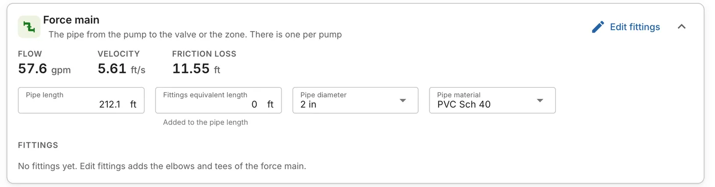
The top of the section shows the Flow, the Velocity and the Friction loss. Below them:
| Field | What it is |
|---|---|
| Pipe length | From the force main on the map. |
| Fittings equivalent length | The fittings' length, added to the pipe length. |
| Pipe diameter and Pipe material | The pipe's size and material. A change updates the friction loss. |
Click Edit fittings to add the elbows and tees of the force main. Enter a count for each fitting, then click Save fittings. Each fitting adds its equivalent length.
Valve
When the network has more than one zone, a distribution valve splits the doses between them. The Valve section shows its manufacturer, model and outlets, and its requirements: the inlet and outlet pipe sizes, the height of the valve and the maker's minimum flow.
Valve friction loss is your value for the loss through the valve. It is added to the TDH. The predicted loss, from the valve's flow data, shows under the field.
Zones
A zone is one part of the pressure network, with its manifold and laterals, and gets all the flow of one dose. Each zone has its own section, such as Zone 1.
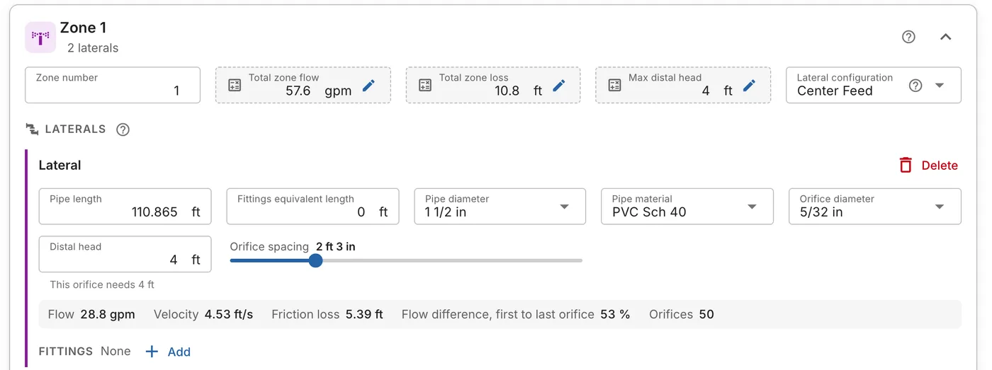
The top of the zone shows:
| Field | What it is |
|---|---|
| Total zone flow | The flow of every orifice, emitter or nozzle in the zone. |
| Total zone loss | The friction loss in the zone's manifold and laterals. |
| Max distal head | The highest pressure any part of the zone needs at its far end. |
| Lateral configuration | Where the laterals are fed, for example Center Feed. Another configuration works out the laterals and manifolds again. |
Laterals
A lateral is a pipe with small orifices that deliver the effluent to the soil under pressure. Each lateral has:
- Pipe length, Fittings equivalent length, Pipe diameter and Pipe material.
- Orifice diameter. The orifice limits the flow.
- Distal head. The pressure at the far end of the lateral. The hint under it says what the orifice needs, for example This orifice needs 4 ft.
- Orifice spacing. Drag the slider to change it.
Under the fields, a row gives the lateral's Flow, Velocity, Friction loss, the Flow difference, first to last orifice and the number of Orifices. Click Add next to Fittings to add the lateral's fittings.
Move puts a lateral in another zone. Delete takes it out of the design.
Manifolds, drip runs and spray heads
- Manifold. The pipe that feeds the zone's laterals from the force main or the valve. It has a pipe length, diameter, material and fittings.
- Drip run. Tubing with drip emitters, for a drip system. It has the run length, the drip tubing, the emitter spacing, the required distal head and the flow rate.
- Spray head. For a spray system: the order of the head along the zone, the spray head and nozzle, and the arc. The nozzle sets the flow and the pressure the head needs.
The checks warn when a lateral, run or head is outside your area's rules.
Pump
The Pump section shows the pump picked for the network's highest zone flow and its TDH.
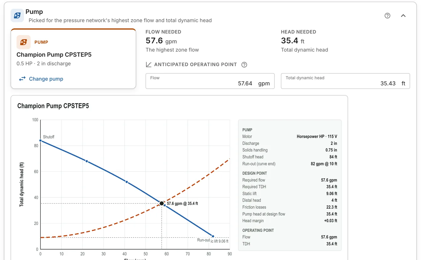
- The pump card gives the pump's name, horsepower and discharge size.
- Flow needed and Head needed are the required flow and the TDH.
- Anticipated operating point is where the pump's curve meets the system curve: the flow and head the pump is expected to run at.
Change the pump
Click Change pump to see the pumps that fit this network. The Select A Viable Pump list draws each pump's curve against the network. Search the list, then click Select.
If no other pump fits, Details says No other pumps fit this network. Change the pressure network, then update the pump to get a new list.
The pump curve
The chart plots the pump's curve (blue) against the system curve (dashed). The dot where they cross is the operating point. Beside the chart, a table gives:
- Pump: the motor, discharge size, solids handling, shutoff head and run-out.
- Design point: the required flow and TDH, the static lift, the distal head, the friction losses, the pump's head at the design flow and the head margin.
- Operating point: the flow and TDH where the curves cross.
Download PDF saves the curve and its values on a page of their own. The same curve prints on the report's dosing detail sheet.
The pump dimensions (Pump height, Pump intake height and Solids handling size) are used by the max draw-down setting in Dosing.
Dosing
The Dosing section sets the dose method, the dose, the dose tank and the floats. For a timed dose, it also has the timer. See Dose Tank and Floats.
Dosing text holds the calculations printed on the dosing detail sheet: the max draw-down calculation and the reserve and surge calculation. Change the wording here.
For a spray system, Precipitation rates gives the hourly and daily rates the spray heads put on the spray area, as printed on the report.
When the pump needs updating
The step bar warns when the pump no longer matches the design:
| Warning | What to do |
|---|---|
| The pressure network changed: update the pump | Click Update pump. Details works out the needs again and finds the pumps that fit. |
| No pump selected | Click Find a pump. You must pick a pump before you can generate the report. |
When the step is done, its caption in the step bar shows the required flow and the TDH, for example 57.6 gpm @ 35.4 ft.