Drip Distribution
How this system works
Drip systems were designed as a method of applying small amounts of wastewater with drip emitter technology. These systems have the ability to typically be installed on steep slopes, heavy woods, or other tough sites. Typically, these systems require more technology including a timed-dosing control panel and some form of advanced treatment prior to discharging the water to the emitter tubing.
Common Components Involved
Septic Tanks
The function of septic tanks in septic systems are to hold back the solid wastes and move on the wastewater. These are normally concrete tanks in the ground which may or may not contain separated compartments. Septic tanks are often crucial part in a septic design. Septic system designs often site septic tanks based first on the local concrete manufacturer. Often times, the capacity of the septic tank sited is dependent on which manufacturer is used. Some manufacturers have longer wait times to manufacturer specific septic tank capacities.
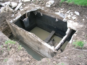
Here is a collapsed septic tank. Visible is the multi-compartments and large volume.
Septic Tank Materials
Some septic tanks are made of alternate materials other than concrete, including polyethylene or fiberglass. Some benefits to utilizing these alternate materials is that they are lightweight and can be carried easier with a chain and a small excavator machine. Some septic tanks are so lightweight they can be lifted with several people.
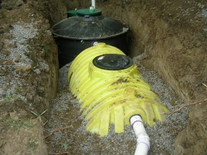
A polyethylene plastic septic tank. Lightweight but often more expensive than concreted.
The water from septic tanks is sometimes called septic effluent. The term septic itself means without oxygen and septic effluent is composed mostly of bacteria and human feces. It is a highly contaminated liquid and human contact is dangerous. Septic tank effluent contains particles of sewage of size 1/16 to 3/16 inch in diameter. The waste strength is measure in Biological Oxygen Demand or BOD.
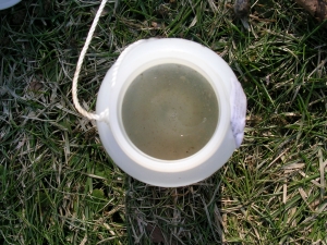
Septic tank effluent is high in solid wastes and pathogens. It must be further treated.
Septic Tank Function
The function of septic tanks in septic systems are to hold back the solid wastes and move on the wastewater to further treatment. The solids can then be pumped at given intervals. The pumping frequency depends on the number of residents in the home and the capacity of the septic tank
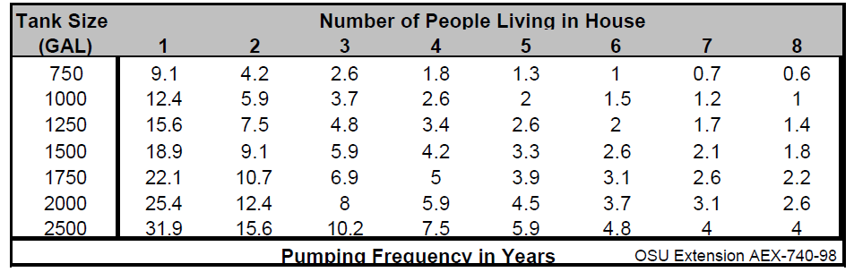
Here is a septic tank pumping lookup charge based on residents and capacity.
Secondary Treatment
A treatment train is just a combination of technologies (active and passive) in a series that the water flows through. Secondary treatment is the use of aeration or filtration to further remove pollutants from the water as it moves through the treatment train.
Many advanced treatment systems are one tank with multiple chambers inside the tank. the secondary treatment compartment usually utilizes aeration, filtration, or a combination of both. the product of secondary treatment is usually a wastewater of significantly less polluted than primary wastewater.
How much of my yard will this take up?
I understand most concerns of homeowners is the impact this will have on their outdoor living space. The combination of tanks required to retain the solids and provide secondary treatment will be completely installed below ground. Unfortunately, it is required to provide access to the tank components through lids that extend at least 2 inches above the ground. The footprint of the tanks is generally 8 ft. wide x 20 ft. long and must be installed downslope of the house. The sewer main will be exiting the house below the final grade and fall at a general 1% slope towards the primary tanks.
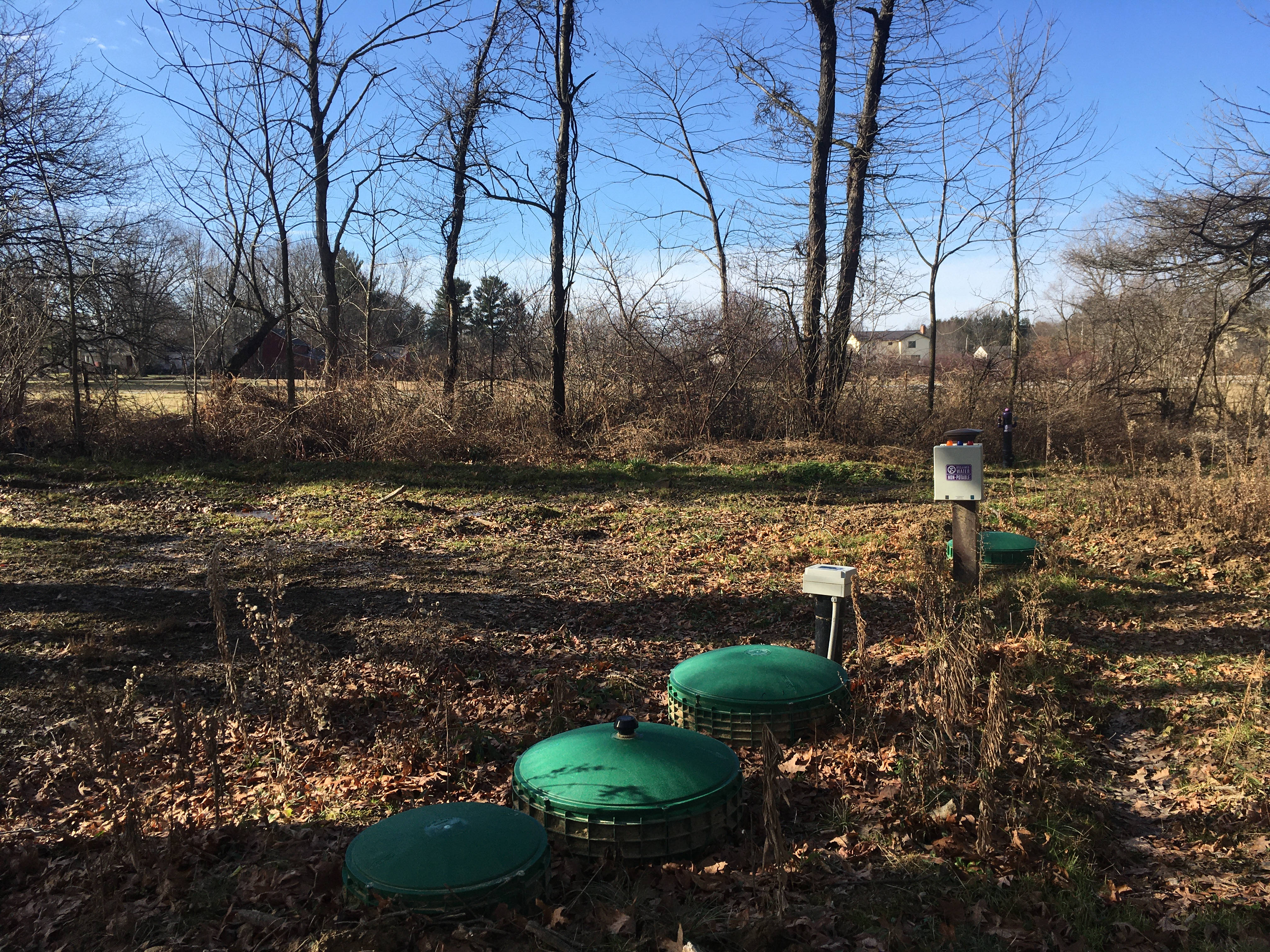
Seen above are the typical green lids, generally 3 lids per treatment tank and one or two lids for the dosing tank. Also seen is a control panel which can alternatively be mounted on the house at a greater cost.
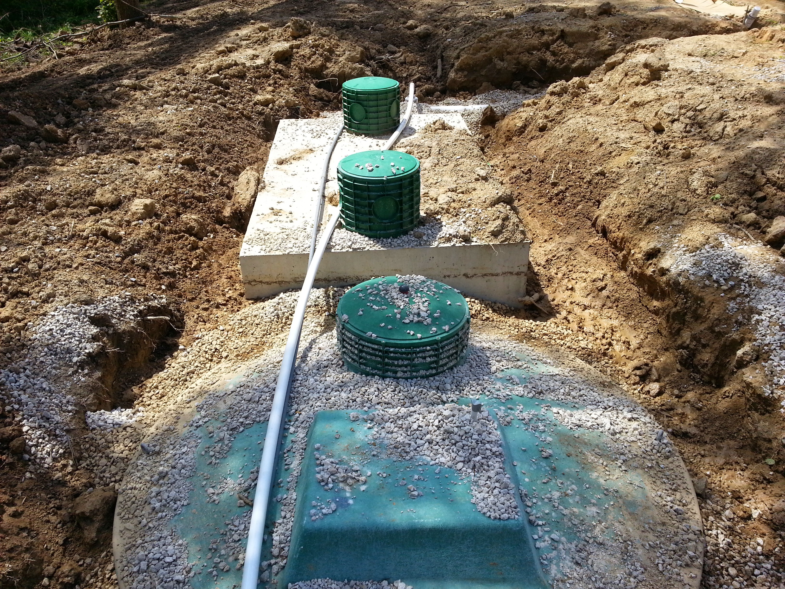
Above you can see the tanks without soil and grass cover. These tanks require electricity to power the aeration motors and control panels.
There are a two main different methods of secondary treatment and many, many proprietary products market and also non-proprietary approved proven construction methods for secondary treatment:
Maintenance required for secondary treatment units are typically recommended at 6 month by the manufacturer. The maintenance includes ensuring any aeration motor is functioning properly and free from obstruction and any filtration is cleaned.
Uniform Pressure-Micro Distribution
Pressure Distribution is not a new concept. It has been used in other states for decades to alleviate the problem of discharging wastewater into clayey soils. The main idea is to evenly distribute the wastewater load evenly over the entire designed soil absorption area. This is done through drip distribution by pumping the wastewater into a pressurized drip tubing and through the emitters slowly drip out approximately 0.25 gallons per square foot of soil.
The drip distribution system has a solenoid valve system (with electrically-switch opened valves) directs the wastewater to different areas of the property. These areas are called zones. Each zone is engineered to absorb a portion of the wastewater. Prior to discharge to the designated zone, the wastewater passes through a disk filter.
A drawing of a disk filter, common with drip distribution systems
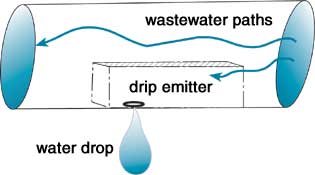
Here is a drawing of the emitter technology and how they work inside the tubing
The drip tubing can be installed in wooded areas, or be plowed into the ground with a vibratory plow
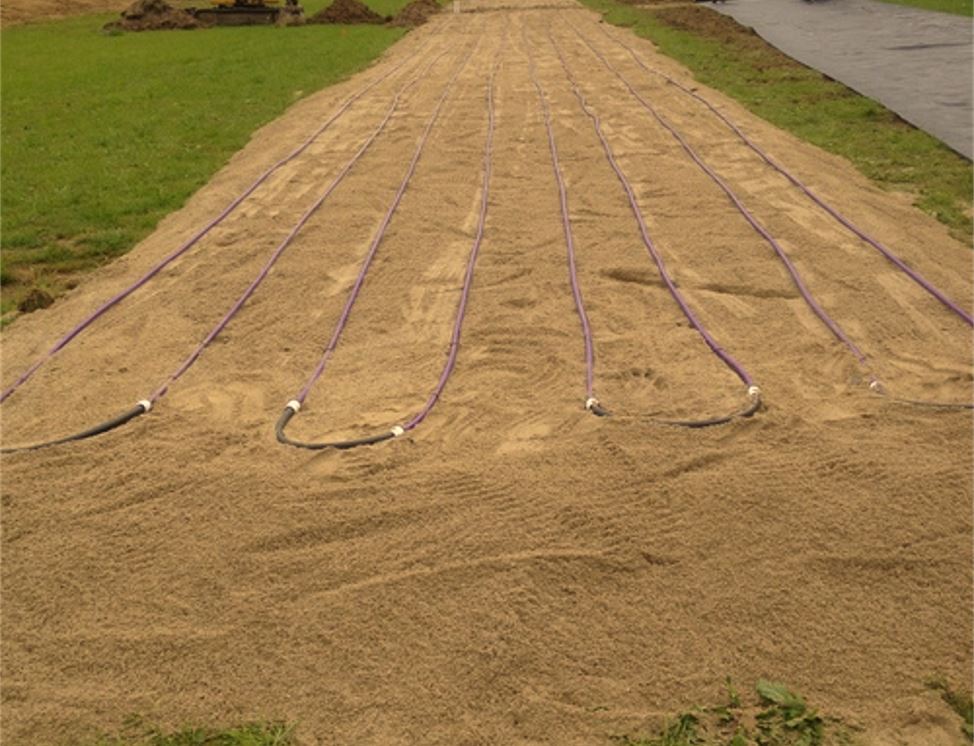
Sand is sometimes required to be installed underneath the drip tubing
Drip Components
Supply Line - pressurized piping discharging from a zone valve (from a Distribution Method)
Return Line - gravity flow piping discharging from Lateral features (extended linestring points)
Dripper Line - specialized pressurized small diameter tubing with pressure compensating drip emitters…sold per flow rates
Zone - a dripper field of dispersal that has its own solenoid valve, represented by a Distribution Bed
Headworks - specialized valve/filter systems that are a plug and play product for contractors. These are represented by Distribution Method features. There are pressure and pumping requirements that must be validated, electrical and frost protection requirements. Headworks usually contain : a disk filter, (n) solenoid valves where n = number of zones
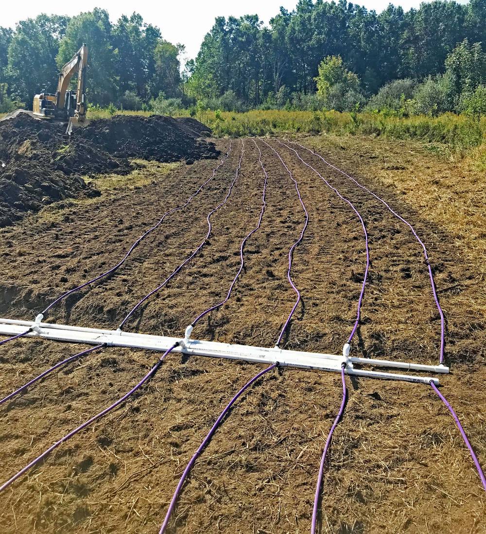
This image shows a center fed at-grade drip zone. The contractor has stagged topsoil and is ready to cover the field.
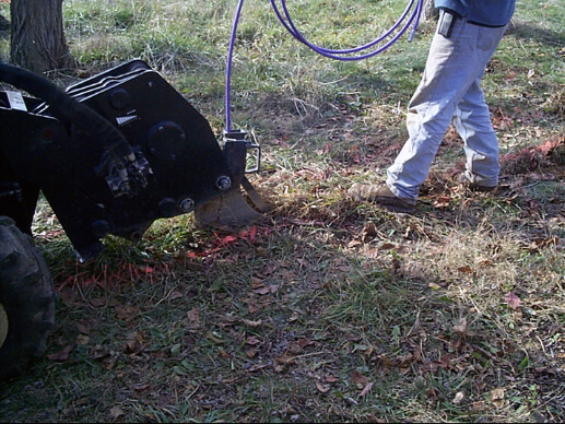
This image shows a drip field being plowed into the ground using a vibratory plowplo
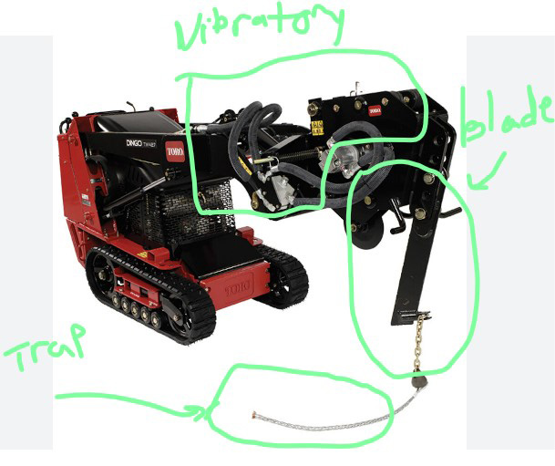
This image shows a vibratory plow. The dripper piping is fed into the trap and the blade cuts through the soil as the unit vibrates.