
Distribution Method
The distribution method is the point where the effluent is split between the trenches, beds or zones of the absorption area. By gravity, a distribution box splits it evenly. Under pressure, a valve or a headworks sends each dose to one zone at a time. A dosing flout or siphon doses the field without a pump. A hydrosplitter takes the dose from a pump and splits it evenly between gravity outlets.
On the map it is a point between the pipe from the tanks and the pipes to the field. The Distribution tool adds it, and can draw the pipes from it to each trench for you.
Distribution method types
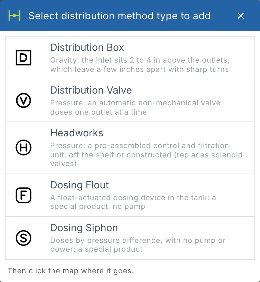
Click Distribution in Tools > Septic design > System. Select distribution method type to add lists the six types:
| Type | Map symbol | What it is | Pipes it draws |
|---|---|---|---|
| Distribution Box | White square, D | Gravity: the inlet sits 2 to 4 in above the outlets, which leave a few inches apart with sharp turns. | A Distribution Main to each trench |
| Distribution Valve | White circle, V | Pressure: an automatic non-mechanical valve doses one outlet at a time. | A Manifold to each trench |
| Headworks | Larger white circle, H (it stands for the 24 in riser it sits in) | Pressure: a pre-assembled control and filtration unit, off the shelf or constructed. It replaces solenoid valves. | A Manifold to each trench |
| Dosing Flout | White rounded square, F | A float-actuated dosing device in the tank: a special product, no pump. | A Distribution Main to each trench |
| Dosing Siphon | White circle, S | Doses by pressure difference, with no pump or power: a special product. | A Distribution Main to each trench |
| Hydrosplitter | White hexagon, H | Pump to gravity: a dose pump feeds a pressure-operated splitter whose orifices send an equal share of each dose to every outlet (for example Orenco's HSA). | A Distribution Main to each trench |
Dosing Flout is the product's name, spelled that way on purpose.
Pick the type the system really uses: Details reads it to work out the pressure network and the elevations. A gravity system (trenches, cut and fill, AES or ATL) usually takes a distribution box, and a pressure system (mound, low pressure pipe, drip) a valve or a headworks.
Add a distribution method
- Click Distribution in the System group (Add a distribution method: pick its type).
- Pick the type. Then click the map where it goes.
- The dialog opens, titled with the type. Fill in its fields (see below). You can still change the type at the top, under Distribution method type.
- Click Draw and the type, for example Draw Distribution Box.
Cancel takes the point off the map. While the tool is on, the tile is blue: click it again to stop placing distribution methods.
Draw the system's trenches first, so the tool can draw the pipes to them. Snapping helps the pipes meet the distribution method: see Snapping.
Distribution box
| Field | What to enter |
|---|---|
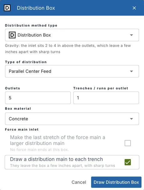
| Type of distribution | How the trenches are fed: Parallel End Feed, Parallel Center Feed, Sequential End Feed or Sequential Center Feed, or your configuration's own list. |
| Outlets | The number of outlets. It starts at the number of trenches drawn, or at the number of distribution pipes in an ATL or AES bed. |
| Trenches / runs per outlet | How many trenches each outlet feeds. The default is 1. |
| Box material | The box, for example Concrete (the default). |
Force main inlet. When a force main from a pump ends at the box, tick Make the last stretch of the force main a larger distribution main to slow the flow before it enters the box. Then set the Diameter (3, 4 or 6 in) and the Length. 4 in and 3 ft are recommended. The last stretch of the force main is replaced by a distribution main of that size. When no force main ends at the box, the option is greyed out (No force main ends at this box.).
Draw a distribution main to each trench draws the distribution mains from the box. They leave the box a few inches apart and turn sharply towards their trench, the way they are laid. In an ATL or AES bed the option reads Draw a distribution main to each distribution pipe: a main goes to each pipe in the bed, not to the bed's trench line.
The box itself. Select the box on the map: its properties show Number of outlets and a D-box product search. Type a maker or a size (for example 6 hole): the catalog's boxes with the box's number of outlets come first, marked Fits. Once you pick one, the product card under it shows its photo, its distributors near the site and its price. Without a product, the box is priced from your area's d-box price list, by its outlets and material.
Distribution valve
| Field | What to enter |
|---|---|
| Feed | End Feed, Center Feed or Double Center Feed. |
| Valve product | The valve. landplan.io picks one by the number of outlets: one model for up to 4 outlets, another for more. |
| Outlets and Trenches / runs per outlet | The number of zones, and the trenches each one doses. |
| Valve box material | The box the valve sits in, for example Plastic (the default). |
Draw a manifold to each trench draws a manifold from the valve to each trench.
Headworks
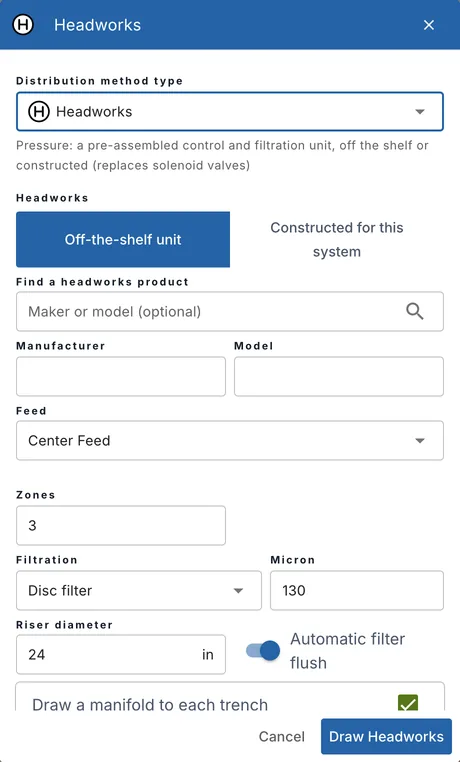
A headworks is a pre-assembled unit with the filters and valves of a drip or pressure system, usually in a riser.
| Field | What to enter |
|---|---|
| Headworks | Off-the-shelf unit or Constructed for this system. |
| Find a headworks product | Search by maker or model. The units sold near the site come first. Pick one to fill in Manufacturer and Model, or type them yourself. |
| How it is constructed | For a constructed headworks: the filter, valves and controller, sized for the system's flow. |
| Feed | End Feed, Center Feed or Double Center Feed. |
| Zones | The number of zones. It starts at one zone for every two trenches drawn. |
| Filtration and Micron | Disc filter (the default), Screen filter or Spin filter, and its rating: 130 micron by default. |
| Riser diameter | The riser it sits in: 24 in by default. |
| Automatic filter flush | On by default. |
Draw a manifold to each trench draws a manifold from the headworks to each trench.
Dosing flout and dosing siphon
Both dose the field without a pump.
| Field | What to enter |
|---|---|
| Find a dosing flout product or Find a dosing siphon product | Search by maker or model, or type the Manufacturer and Model yourself. |
| Feed | End Feed, Center Feed or Double Center Feed. |
| Siphon diameter | Dosing siphon only: 4 in by default. |
| Dose volume | The volume of each dose, in gallons. |
| Drawdown per dose | How far the tank level drops with each dose, in inches. |
| Average discharge | Dosing siphon only: its average flow, in gal/min. |
Draw a distribution main to each trench draws the distribution mains to the field.
Hydrosplitter
A hydrosplitter is a pressure-operated splitter: a dose pump sends each dose to it, and flow-control discs (orifices) split it equally between its outlets, which run by gravity to the trenches. Oregon allows one for equal distribution (OAR 340-071-0220(4)(a)(B)). Orenco's Hydrosplitter (HSA) is built for each drainfield; its standard models have two to eight outlets.
| Field | What to enter |
|---|---|
| Find a hydrosplitter product | Search by maker or model (for example HSA100-04-10). Hydrosplitters are built to order, so few dealers list them: when none is listed for sale, the search shows Orenco's own catalogue, with no price (ask Orenco or a dealer). Or type the Manufacturer and Model yourself: Orenco Systems and HSA to start with. |
| Feed | End Feed, Center Feed or Double Center Feed. |
| Outlets and Trenches / runs per outlet | The number of outlets (one per trench to start with), and the trenches each one feeds. |
Draw the Force Main from the pump to the hydrosplitter yourself. Draw a distribution main to each trench draws the gravity mains from its outlets. The report lists it in the component table as Hydrosplitter, with its outlets.
The pipes it draws
When you click Draw, landplan.io places the distribution method and, if you ticked it, draws a pipe to each trench or lateral of the system:
- Distribution Mains from a distribution box, a dosing flout, a dosing siphon or a hydrosplitter.
- Manifolds from a distribution valve or a headworks.
If there is no trench or pipe line to connect to, the distribution method is added without pipes, and a message says so. Draw the pipe from the tanks to it yourself: a Distribution Main by gravity, or a Force Main from a pump. See Pipe Tools.
To change a distribution method later, select it on the map and edit its properties. See Component Properties.
From Smart design
Smart design has a Distribution method step for the systems that need one, such as leaching trenches and low pressure pipe. Place it for me adds a distribution box for a gravity system (leaching trenches, cut and fill, AES and ATL) and a distribution valve for a pressure system, at the side of the field nearest the tanks, and draws the pipes to each trench. See Smart Design and Auto Design.
Distribution methods drawn before these types
Distribution methods drawn before the five types keep working, and keep every value they had. A solenoid valve opens as a constructed Headworks, with its valves as zones. A manual non-mechanical valve or a dual alternating pump reads as a Distribution Valve.