Mounded Leaching Systems
How this system works
Mound systems were designed as a method of onsite wastewater treatment in poor soil. These systems commonly use sand fill as the method of treatment to remove pollutants prior to reaching the soil. Clay soil can prevent downward movement of the water through the soil and cause surfacing of poorly treated sewage and public health risks.
The following is a step by step explanation of optional and required components in a mounded leaching system
Common Components Involved
Septic Tanks
The function of septic tanks in septic systems are to hold back the solid wastes and move on the wastewater. These are normally concrete tanks in the ground which may or may not contain separated compartments. Septic tanks are often crucial part in a septic design. Septic system designs often site septic tanks based first on the local concrete manufacturer. Often times, the capacity of the septic tank sited is dependent on which manufacturer is used. Some manufacturers have longer wait times to manufacturer specific septic tank capacities.
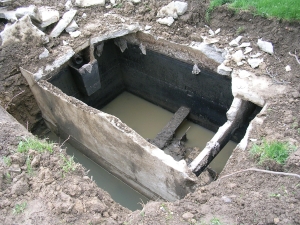
Here is a collapsed septic tank. Visible is the multi-compartments and large volume.
Septic Tank Materials
Some septic tanks are made of alternate materials other than concrete, including polyethylene or fiberglass. Some benefits to utilizing these alternate materials is that they are lightweight and can be carried easier with a chain and a small excavator machine. Some septic tanks are so lightweight they can be lifted with several people.
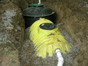
A polyethylene plastic septic tank. Lightweight but often more expensive than concreted.
The water from septic tanks is sometimes called septic effluent. The term septic itself means without oxygen and septic effluent is composed mostly of bacteria and human feces. It is a highly contaminated liquid and human contact is dangerous. Septic tank effluent contains particles of sewage of size 1/16 to 3/16 inch in diameter. The waste strength is measure in Biological Oxygen Demand or BOD.
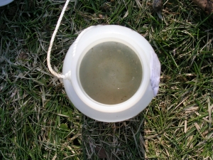
Septic tank effluent is high in solid wastes and pathogens. It must be further treated.
Septic Tank Function
The function of septic tanks in septic systems are to hold back the solid wastes and move on the wastewater to further treatment. The solids can then be pumped at given intervals. The pumping frequency depends on the number of residents in the home and the capacity of the septic tank

Here is a septic tank pumping lookup charge based on residents and capacity.
Secondary Treatment
A treatment train is just a combination of technologies (active and passive) in a series that the water flows through. Secondary treatment is the use of aeration or filtration to further remove pollutants from the water as it moves through the treatment train.
Many advanced treatment systems are one tank with multiple chambers inside the tank. the secondary treatment compartment usually utilizes aeration, filtration, or a combination of both. the product of secondary treatment is usually a wastewater of significantly less polluted than primary wastewater.
How much of my yard will this take up?
I understand most concerns of homeowners is the impact this will have on their outdoor living space. The combination of tanks required to retain the solids and provide secondary treatment will be completely installed below ground. Unfortunately, it is required to provide access to the tank components through lids that extend at least 2 inches above the ground. The footprint of the tanks is generally 8 ft. wide x 20 ft. long and must be installed downslope of the house. The sewer main will be exiting the house below the final grade and fall at a general 1% slope towards the primary tanks.
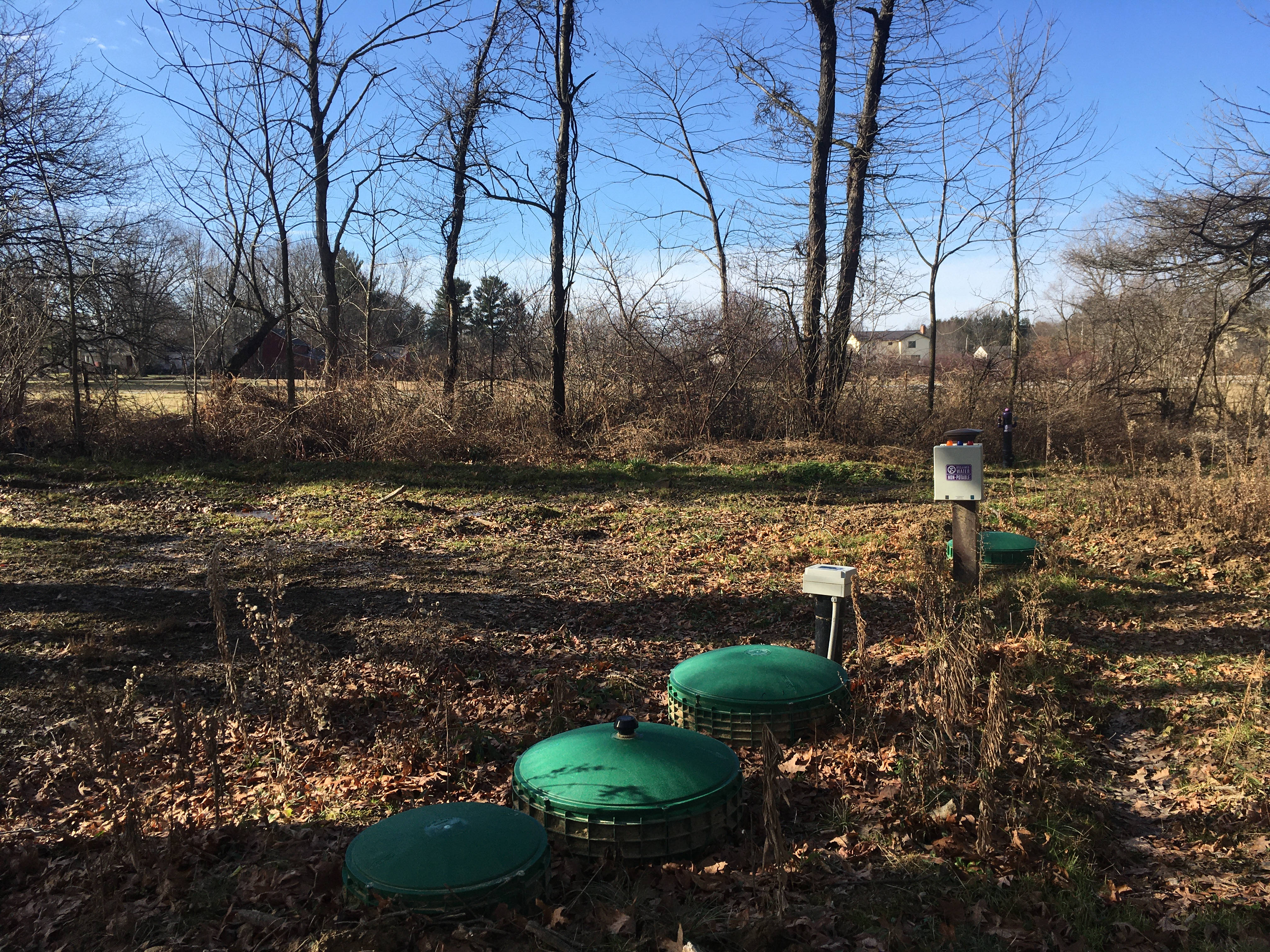
Seen above are the typical green lids, generally 3 lids per treatment tank and one or two lids for the dosing tank. Also seen is a control panel which can alternatively be mounted on the house at a greater cost.
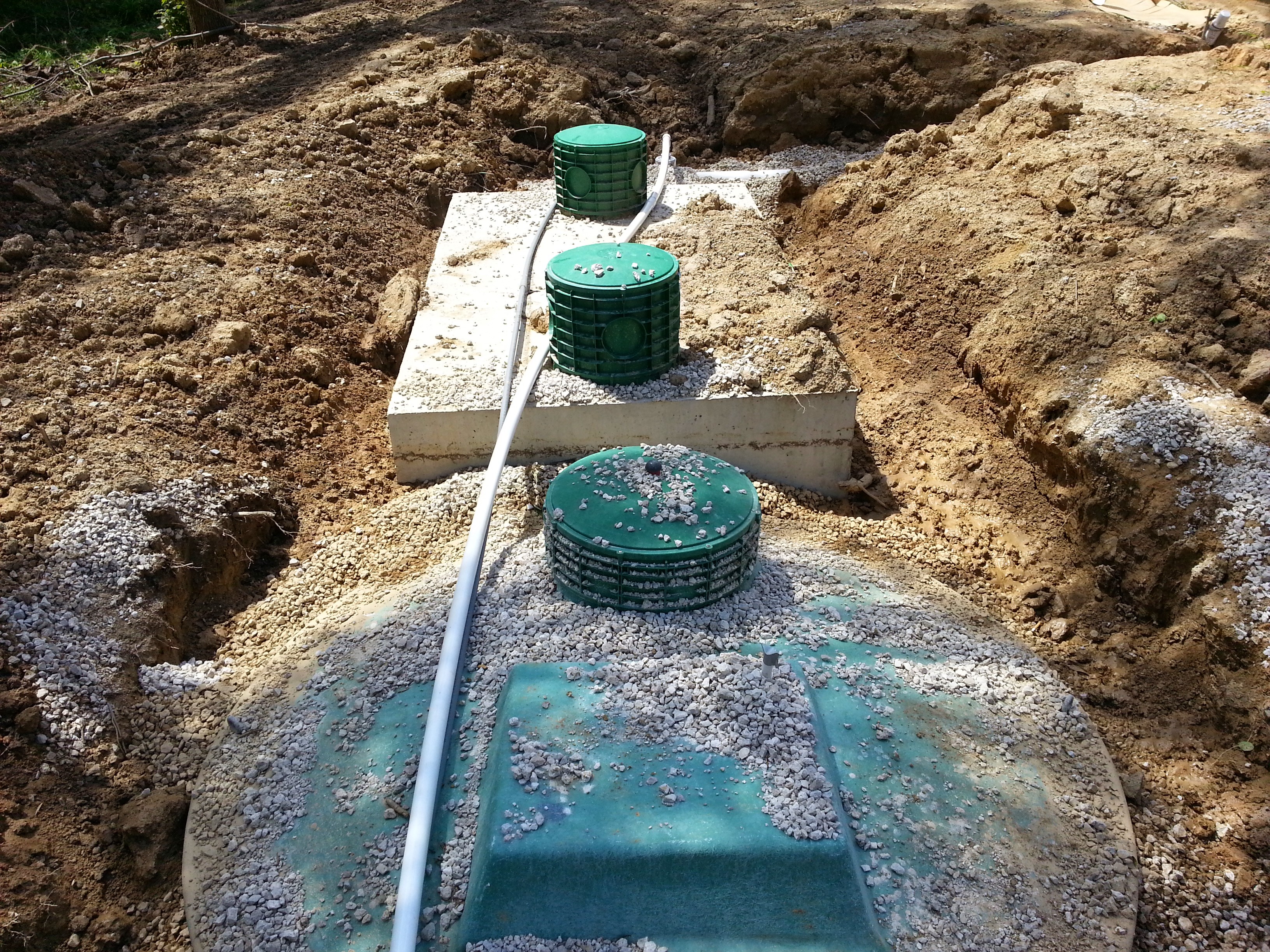
Above you can see the tanks without soil and grass cover. These tanks require electricity to power the aeration motors and control panels.
There are a two main different methods of secondary treatment and many, many proprietary products market and also non-proprietary approved proven construction methods for secondary treatment:
Maintenance required for secondary treatment units are typically recommended at 6 month by the manufacturer. The maintenance includes ensuring any aeration motor is functioning properly and free from obstruction and any filtration is cleaned.
Uniform Pressure Distribution
The trench running along the centerline of the mound contains a pipe network. This pipe contains small diameter holes drilled by the installation contractor. When the pump is turned on the pipe network becomes pressurized and the water distributes evenly over the entire length of the mound.
Pressure Distribution is not a new concept. It has been used in other states for decades to alleviate the problem of discharging wastewater into clayey soils. The main idea is to evenly distribute the wastewater load evenly over the entire designed soil absorption area. This is done by pumping the wastewater into a pressurized piping system with holes that literally squirt the water evenly into the designed media.
Pressurized septic treatment systems are often difficult to design. They provide a unique and difficult problem in selecting the properly sized and spaced holes in the pressure piping. Pressure piping are composed of sections of Force Main, Manifold, and one or more Laterals. Force main sections transmit the water from the dose tank to the manifold. The manifold splits the force main to the laterals. The laterals are sections of the pressure network that distribute the water to the soil, whether by trench or elevated sand bed.
Some problems with designing these systems are there are meeting the square footage per application hole rule and also meeting the requirement for less than ten percent flow loss, all while maintaining two ft. per second velocity.
Often times these systems require a valve system to ensure these rules are met for dosing every area uniformly.
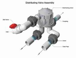
A distributing valve splits flow and alternates dosing different zones.
Steps of Mound Component Construction Visualized
Mound systems must be installed with the centerline running along a natural contour of the land. This is the goal in order to allow equal distribution along the land and in most areas it is required by regulations.
1. Approval/Permit Process.
A designer must identify an area on the land by flagging or staking the centerline of the mound.
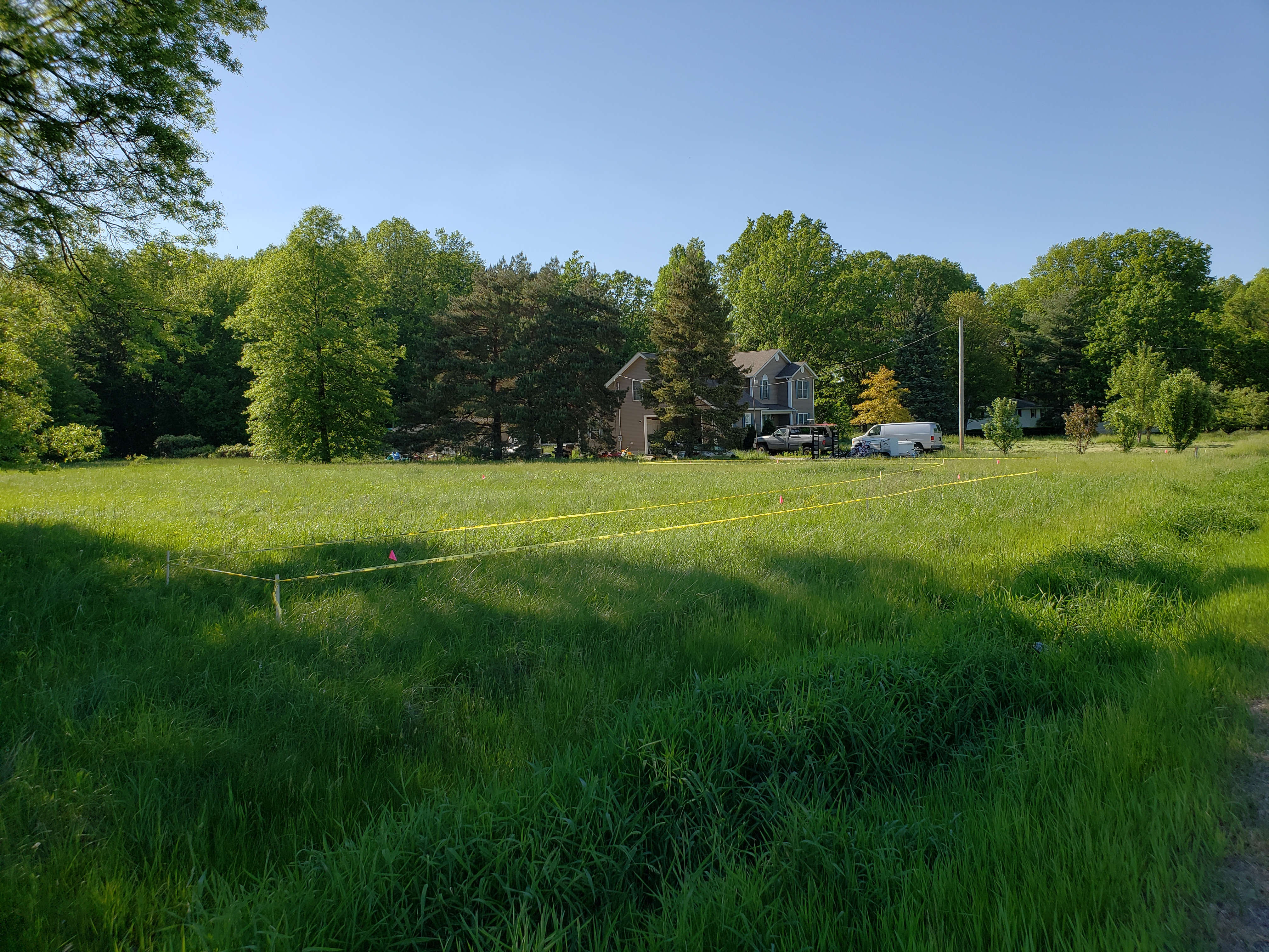
The centerline of the mound is flagged along the natural contour of the land. Typically, local regulators require caution tape around the mound area to protect it from construction
The local regulatory agency has to approve the area and full design plan.
2. Preparing the Mound Area.
If grass is present, the area must be chisel plowed or the sod layer must be broken up, most commonly with an excavator bucket teeth.
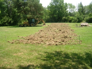
Here the sod/grass layer is broken up with an excavator along the entire mound length
Wooded areas must be cleared not only in the direct mound area but also within 50 ft. of the mound to allow sunlight to hit the mound and promote evaporation/transpiration from the top of the mound.
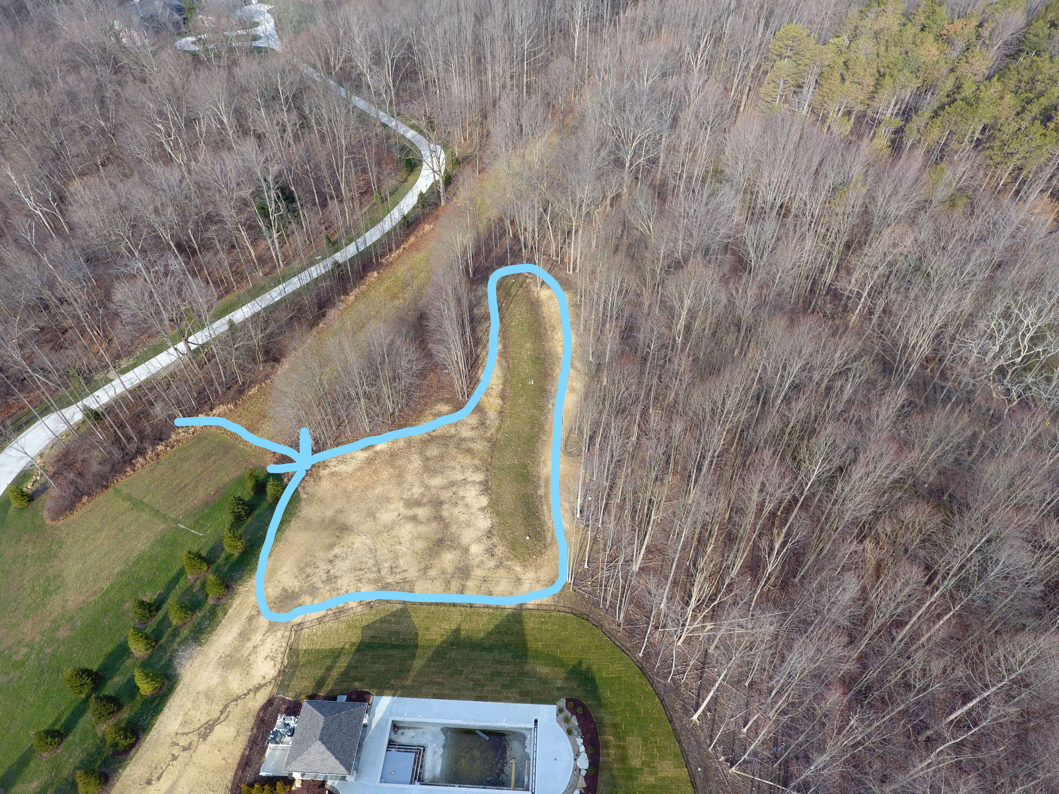
Here is an overhead view of a recently installed mound system and the required tree clearing. It is one of the negative aspects of the requirements of the mound system installation
3.Stockpiling Sand Materials Near the Installation
This system often requires many many deliveries of sand, which is the primary filtration media. One of the other negative aspects of this system is it is very labor intensive. Contractors have to put in a lot of machine labor moving large amounts of materials.
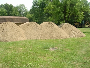
Above you can see the contractor has stockpiled sand near the mound site
Concrete sand seen here contains large particles and is more porous than other finer sands.
4.Install the Force Main to the Mound
The mound system requires a pump and pipe network installation. Contractors often will install the force main to the point of connection to the mound laterals.
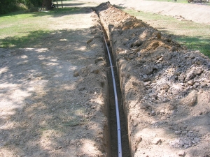
Here the contractor has trenched the force main to the mound
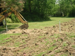
Here you can see the force main installed to the mound center and covered with soil. A standpipe is installed which can later be cut when the laterals are installed. The laterals are the pipe in the network which the small holes are drilled.
5.Installing the Sand
Spreading the sand across the length of the entire mound is a mix of machine and hand labor. It takes a good eye as well as excellent excavator skills to not only shape the mound but to make it look good as well.
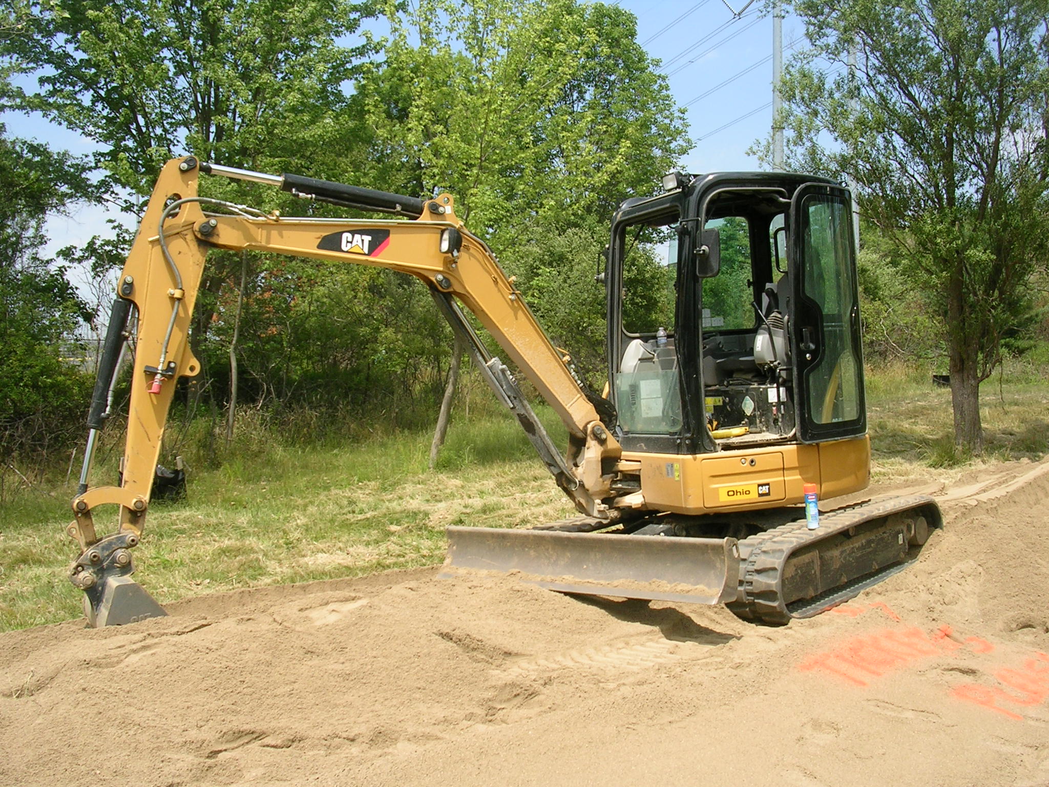
Here a tracked mini excavator is on top of the sand mound providing shape for the downslope
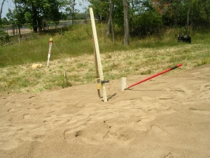
The contractor uses a laser level and rake with a lot of manual labor to finish the final grading on the sand
6.Installing the Center Trench Gravel and Finishing the Pipe Network
The center of the sand mound is typically dug out and gravel is installed. At the near top of the gravel, a laterals connect to the force main to complete the pipe network. There are other construction methods to install the pipe network, but this is a common one.
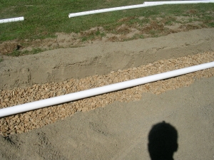
Here the center trench is dug, gravel placed and the lateral pipes installed completing the pipe network
7.Cover with Straw or Landscaping Fabric and Soil
A soil cap of varying depth is installed over the mound. The mound typically is built with a final grade of 3:1 to facilitate water run-off but also allow the homeowner to use a lawnmower on it.
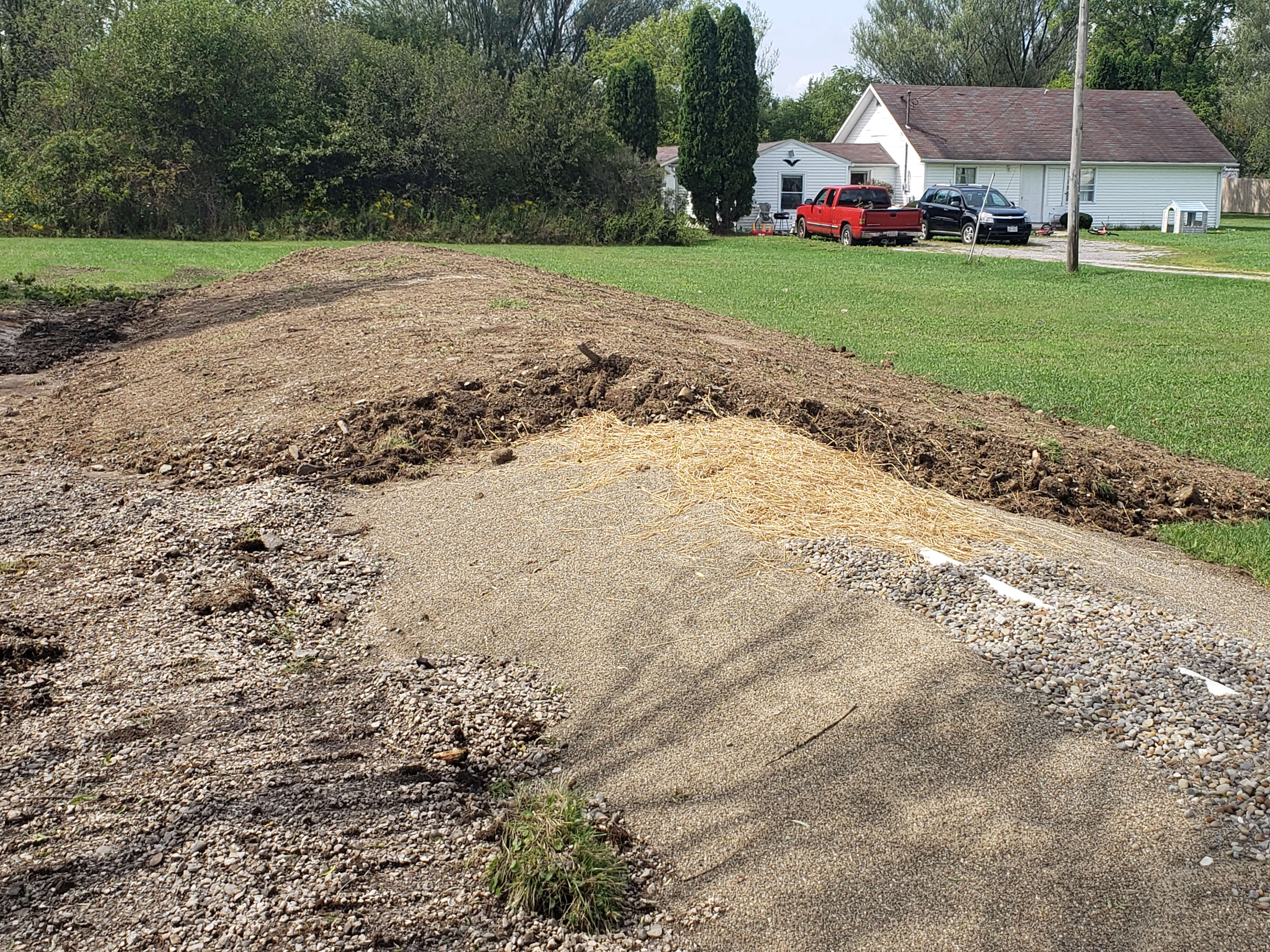
Here you can see the different layers and components of the mound very clearly
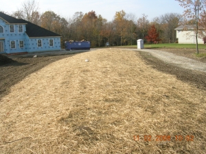
Finished graded mounds are covered with straw and seeded with grass. Note this mound was installed parallel with the driveway