
Large Diameter Pipe (LDP) Systems
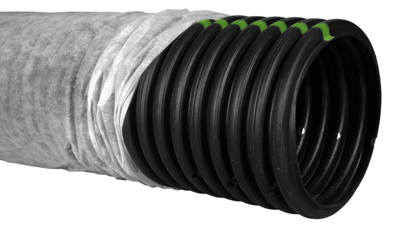
Large diameter pipe (LDP) systems replace the perforated pipe and gravel of a conventional trench with a large plastic pipe, usually 10 to 12 in across, wrapped in fabric or synthetic media. The pipe and its media treat the effluent as well as carry it. Much design work has gone into the perforations and the media around them.
landplan.io designs two LDP products as systems of their own, each as rows of pipe in a bed of sand:
- AES: Infiltrator's Advanced Enviro-Septic®.
- ATL: Infiltrator's Advanced Treatment Leachfield.
Other LDP and gravelless products, such as EZ Flow bundles and Eljen GFS, are media you can pick for a leaching trench system.
The parts an LDP system shares with other systems are described in Common Components.
Sand fill and product approvals
In some areas, sand fill under and around the pipe lets an LDP system be approved on poor soil. Tests of the effluent from these combinations show large reductions in total suspended solids and biochemical oxygen demand. Many regulators accept the test results and allow a smaller system or a shallower installation.
Each product usually has a design and installation manual for each area that approves it. Follow the manual for your area: landplan.io's forms take their defaults from your area's configuration.
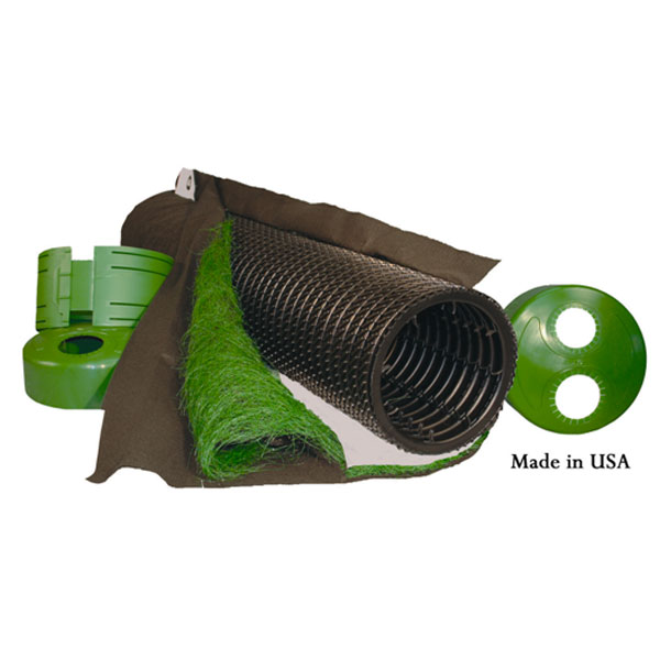
The LDP products
| Product | Maker | In landplan.io |
|---|---|---|
| Advanced Enviro-Septic™ (AES) | Infiltrator Water Technologies | A system of its own (AES), or a trench media |
| Advanced Treatment Leachfield (ATL) | Infiltrator Water Technologies | A system of its own (ATL) |
| SB2 Leach Bed Pipe | ADS | Where your configuration lists it |
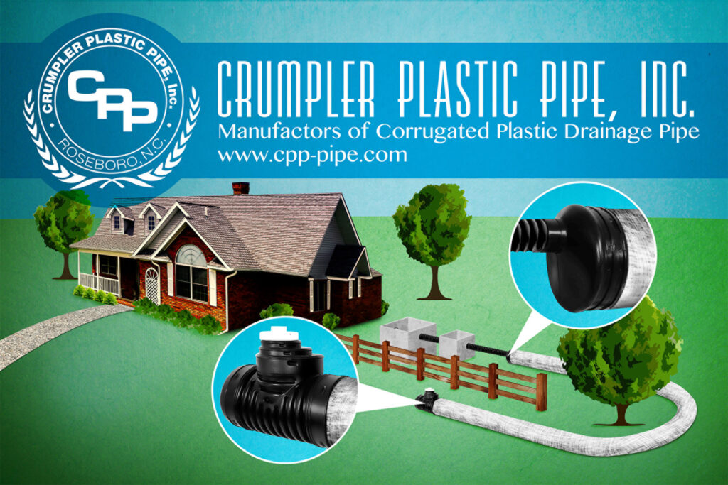
| Spread-Rite™ Septic Pipe | Crumpler Plastic Pipe Inc. | Where your configuration lists it |

Design an AES or ATL system in landplan.io
- Add the soil test, the house, the sewer main and the tanks. See Septic Design.
- In Tools > Septic design > System, click Trench and draw the first row of pipe along the contour. See Trench Tool.
- Click Contour and choose Infiltrator Advanced Enviro-Septic® (AES) or Infiltrator Advanced Treatment Leachfield (ATL). Set it up in the Design form and click Draw System.
- Click Distribution to add a distribution box, and draw the distribution mains. See Distribution Method.
- Open Details to check the sizes and the elevations, and to make the report.
For each step of the contour tool, see Contour Systems. Replacement Area Draw in the editor draws only a replacement area for a future system.
The AES and ATL form
The fields come from your area's configuration, and so do their defaults. These are the main ones:
| Field | What it sets | Typical default |
|---|---|---|
| Distribution Pipe | The product: Advanced Enviro-Septic™ or ATL™ Advanced Treatment Leachfield. | Set by the system |
| Pipe Conduit Length | The length of each row of pipe. | Your line's length |
| Number of Conduit Rows | How many rows of pipe. | 2 |
| Spacing Between Pipe | The distance between rows. | 0.5 ft (AES), 1 ft (ATL) |
| Lateral Configuration | Parallel or Sequential, Center Feed or End Feed. | Parallel End Feed |
| Sand Depth Under Pipe | The sand under the pipe. | 12 in (AES), 6 in (ATL) |
| Depth of media above the distribution pipe | The sand over the pipe. | 6 in (AES), 0 in (ATL) |
| Depth Into Existing Soil | How deep the bed sits. | From your area's rules |
| Sand Upslope Spacing, Sand Downslope Spacing and Sand End Spacing | The sand beyond the pipe. | 1 ft |
| Depth Soil Cover | The cover over the bed. | 6 in |
| Number of Air Vents and Air Vent Height | The bed's venting. | 1 vent, 3 ft (AES) |
The bar along the bottom gives Basal Width, Estimated Sand and Total Computed Area.
Your area's rules decide some values for you:
- Minimum length. An ATL system needs a minimum total length of pipe by design flow: 140 ft at 240 gpd, up to 770 ft at 1,310 gpd (Indiana has its own table). An AES system has its own minimum length by bedrooms or flow.
- Sand depth. In Ohio a depth credit over 1 ft (AES) or 0.5 ft (ATL, at grade) sets the sand depth. For ATL, Indiana uses 12 in of sand when the bed is no more than 4 in into the soil.
- Depth into the soil. In Ohio and Indiana the ATL depth comes from the limiting condition, at most 36 in in Indiana.
What Smart design and Auto design do
Both can generate an AES or ATL system from your configuration's form. They are fed by gravity, so Smart design adds a distribution box with a distribution main to each row, unless the soil test's system option calls for a pump. In Auto design, choose AES proprietary (AES) or ATL proprietary (ATL) under System.
See Smart Design and Auto Design.
Checks
The editor checks an AES or ATL bed as it does the other sand beds:
- Vertical separation to the limiting condition and In-situ soil above the limiting condition.
- Sand treatment depth under the media.
- Cover over the whole sand fill, and the side slopes where the bed is above grade.
- Observation port follows the design manual's placement and Drawn length matches the design.
Your configuration adds the area check and, where it sets one, the minimum soil cover. See the mound's Checks for what each check compares.
In the report
- Cross Section (CS-1): the bed with its rows of pipe, the sand and the cover.
- Top View (TV-1): the rows of pipe from above.
- Hydraulic Profile (HP-1): the house, the tanks, the distribution box and the bed.
- Calculations: the flow, the soil and the area.
See The report sheets.