
Septic System Design Drawings: What a Plan Shows
Short answer: a septic design drawing set usually has a site plan (the lot seen from above, with the house, tank, drain field, wells and setbacks), a cross section through the drain field, a hydraulic profile of the flow from the house to the soil, the soil test locations and logs, and the calculations that size the system. Pumped systems add a dosing detail. Which sheets your county requires, and who may sign them, is set by local rules.
This guide walks through each sheet: what it shows, why the health department needs it, and what reviewers look for. At the end we show how landplan.io draws the whole set from a design.
The sheets in a typical permit set
| Sheet | What it shows | Why it's needed |
|---|---|---|
| Site plan (plan view) | The parcel, buildings, wells, water, the tank, the drain field, the reserve area, setbacks, contours | Proves the system fits the lot and keeps its distances |
| Cross section | The drain field cut across, to scale: trench or bed, media, sand, cover, the limiting layer | Proves the vertical separation and the construction |
| Hydraulic profile | Every part from the house to the drain field seen from the side, with elevations | Proves the effluent flows, or that the pump can lift it |
| Top view / system detail | The drain field from above: trenches or bed, laterals, ports, dimensions | Tells the installer what to build |
| Dosing detail | The dose tank, floats, dose volume, pump and its curve | Pumped and pressure systems only |
| Soil logs | Test pit or boring descriptions, depths to the limiting condition, perc results | The basis for the loading rate |
| Calculations | Design flow, loading rate, area, pump head | Lets the reviewer check the numbers |
| Notes | Construction notes, materials, inspection points | What the installer and inspector follow |
Small or simple jurisdictions may accept a site plan with a few details on one sheet; others publish a checklist or a form of their own. Your state's page on septic rules by state is a starting point, and your health department has the final list.
The site plan
The site plan is the sheet everyone looks at first. It is drawn to scale, with a north arrow and a scale bar, and it usually shows:
- Property lines and their dimensions, easements and rights of way.
- Buildings: the house, garage, outbuildings, decks and driveways, existing and proposed.
- Water: wells on the lot and on neighbouring lots within the setback distance, springs, streams, ponds, wetlands, drainage ditches.
- The system: building sewer, septic tank, dose tank, distribution box or force main, drain field, and the reserve or replacement area where one is required.
- Setbacks: the distance from the system to each feature, often drawn as buffers.
- Soil test locations: each test pit, boring or perc hole, labelled to match the logs.
- Topography: contour lines or spot elevations, and a benchmark.
- Flood zones and slopes where they limit the system.
Reviewers check that every part is outside its setbacks, that the drain field sits where the soil was tested, and that nothing (a driveway, a pool, a future addition) will be built over it.
The cross section
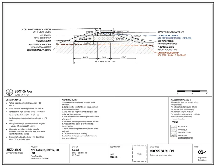
The cross section is the drain field cut across, drawn to scale. For a trench system it shows the trench width and depth, the stone or gravelless product, the pipe, the cover soil and the native soil under it. For a mound it shows the sand fill, the aggregate bed, the laterals, the cap and the side slopes.
The key line on it is the limiting condition: the depth of a seasonal high water table, bedrock or a restrictive layer found in the soil test. The drawing proves that the required depth of unsaturated soil (and sand, for a mound) sits between the bottom of the system and that layer. The EPA's mound fact sheet notes that this separation varies, but is usually between 1 and 4 feet. Your state sets it.
The hydraulic profile
Wastewater has to flow downhill from the house to the tank, and on to the drain field by gravity or by a pump. The hydraulic profile shows the whole path from the side: the building drain, the sewer, each tank, the distribution box or pump and force main, and the drain field, over the existing grade.
A good profile gives, at each point, the station (distance along the path), the ground elevation, the pipe invert (the inside bottom of the pipe) and the cover. From those the reviewer checks:
- that every gravity pipe falls at least the minimum slope,
- that tanks and pipes have enough cover but aren't set too deep,
- for a pumped system, the static lift and the total dynamic head the pump must deliver.
Top view and system detail
The top view is the drain field seen from above at a larger scale than the site plan: each trench or the bed with its length and width, the laterals and their orifices, where the force main feeds them, observation ports and the distribution box. It's the sheet the installer stakes out from.
Dosing detail
Mounds, low pressure pipe, drip and other pressure systems need a pump tank. The dosing detail shows the tank, the floats (pump on, pump off, alarm), the dose volume, the reserve, the pump's model and its curve against the system's required flow and head. See Dose Tank and Floats.
Soil logs and calculations
The soil logs record what was found in each hole: the horizons, their texture and structure, colours that show seasonal saturation, and the depth of the limiting condition, or the timed readings of a perc test. See Perc Test vs Soil Evaluation.
The calculations sheet ties it all together: the bedrooms and design flow, the loading rate taken from the soil, the area or length needed and provided, and for a pressure system the pipe sizes, friction losses and pump selection. See Drain Field Size.
Who may draw and sign septic plans?
That depends on where you are. Depending on the state and the system, plans may be prepared by a licensed onsite designer or installer, a professional engineer, a registered sanitarian or soil scientist, and in some places a homeowner for a simple system. Complex or large systems usually need an engineer's seal. See How to Find a Septic Designer.
Common reasons a drawing is sent back
- A setback is missing or measured to the wrong feature (a neighbour's well is easy to miss).
- The drain field isn't where the soil was tested.
- No reserve area, where one is required.
- The cross section doesn't show the limiting condition, or the separation is short.
- The profile shows a gravity line with too little fall, or a pump without its head calculation.
- The tank or product isn't on the state's approved list.
How landplan.io draws the set
landplan.io draws the design on a real map: give it an address and it brings in the parcel lines, public elevation data (contours from lidar), the NRCS soil survey, water features and flood zones. You place the house, the tanks, the drain field and the pipes, or let Smart design or Auto design place them inside your county's setbacks. From that one design, the report PDF prints:
- Title, with the materials estimate, construction notes and plan contents.
- Hydraulic Profile (HP-1), with stations, grade, inverts, cover, static lift and total dynamic head.
- Cross Section (CS-1), to scale, one per system, with each layer named.
- Top View (TV-1), with dimensions, the force main feed and observation ports.
- Map Print, the site plan, set up in print mode with a title block, legend, north arrow and scale bar.
- Dosing Detail, for pumped systems.
- Calculations, the flow, soil, area and pump numbers.
Change the design and the sheets are drawn again. You can also export the map to DXF or DWG for a CAD workflow.
- Details and the Report PDF: every sheet, with examples.
- Print a Site Plan and Print Settings.
- Contour Systems: the cross section editor.
- Export GPS Points: CSV, shapefile, DXF and DWG.
A licensed professional still checks the plan and signs it. landplan.io does the drafting and the arithmetic so that the professional's time goes to the site and the judgment calls.
Frequently asked questions
Do I need a survey for a septic site plan?
Some counties accept a site plan drawn from parcel maps and field measurements; others require a licensed survey, especially near property lines or for subdivisions. Ask your health department.
What scale should a septic site plan be?
Many jurisdictions name a scale or a minimum sheet size. When they don't, choose a scale at which the setbacks can be read and measured, and always include a scale bar.
What is a hydraulic profile in a septic design?
A side view of the flow path from the house to the drain field, with the elevations of each pipe and tank. It shows that the effluent flows by gravity or what a pump must lift.
Can I draw my own septic plans?
In some states a homeowner may design a simple system on their own property; in most, a licensed designer or engineer must. Check your state's rules on the septic pages by state.
Design it from your address
Create a free account, type the address, and landplan.io draws the site plan, cross section, hydraulic profile and calculations for a system that fits your county's rules.